
Project Index
- TableTop Arcade - Raspberry Pi 3 & RetroPie Setup, Part 1
- TableTop Arcade - Raspberry Pi 3 & RetroPie Setup, Part 2
- TableTop Arcade - Controller & Parts Selection
- TableTop Arcade - Cabinet Construction & Cutting
- TableTop Arcade - Assembly, Electrical, and Painting
- TableTop Arcade - Artwork, Speakers, Marquee
- TableTop Arcade - Wiring and Wrapping Up
- TableTop Arcade - Final Build Pics
Now that the hardware and software to run the emulator has been covered, on to the actual Arcade Cabinet construction. This specific post will mostly cover the controller board, but being that we need something to begin measuring against, lets talk about the cabinet first. I already covered the parts for the Raspberry Pi, but here is the remainder of the parts that will be used for the arcade cabinet.
Arcade Cabinet Parts List
- Arcade Power
- 5 Plug Surge Protector
- Fused switched main inlet socket & power cable
- Display & Sound
- 19" LCD monitor
- HDMI to DVI cable
- USB Powered Speakers
- 3.5mm AUX Cable
- Controls
- 2x Zero Delay USB Encoder (sends button presses to the Raspberry Pi vis USB cable)
- Later upgraded to an Ultimarc I-PAC 2
- 2x 8 Way Classic Arcade Joystick
- 26x Classic Arcade Push Button (Including 1p / 2p Start Push Button)
- 26x Microswitches
- 2x USB Flush Mount Extensions
- Cabinet
- 3/4" MDF board 4ft x 2ft
- 1/2" MDF board 4ft x 2ft
- 1/4" MDF board 4ft x 2ft
- 3/4" x 10ft blue t-molding
- Matte black interior paint
- 12" piano hinge
- 2x Cabinet latches
- Marquee
- 1/8" Plexiglass 4ft x 2ft
- Flexible LED strip kit
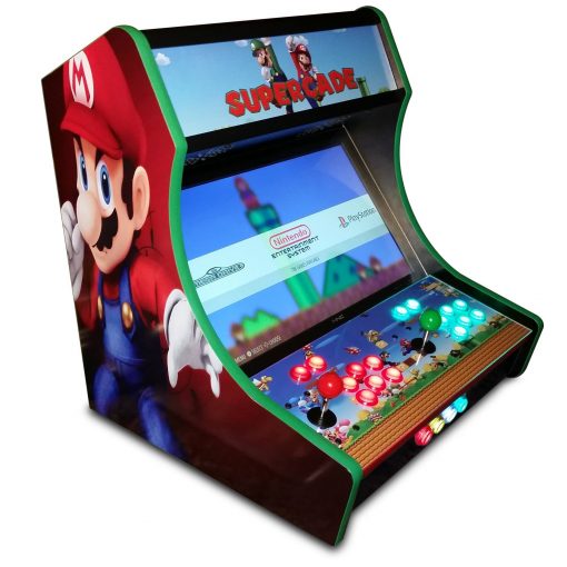
I initially wanted to build a full-size standing arcade cabinet, but decided that it was a bit much for my first attempt. I still plan on making one in the future, and it will be powered by a small PC instead of a Raspberry Pi, but this project was downsized to a Table-top sized design. It will look similar to a standing cabinet, and will house a 19in 4:3 aspect ratio LCD monitor. I will also be adding speakers to the unit and an access panel to the back.
For those that don't want to make their own cabinet from scratch, there are plenty of websites selling kits that will allow you to assemble a cabinet if you don't have all the tools required to build it yourself. Once such site is GameRoomSolutions. They have a really basic kit for around $100, and another kit that is a bit more feature rich (artwork, backlit marquee, etc), similar to what I am building, for around $220.
I was able to find a compelling design for the table-top cabinet on Instructables, made by user Rolfebox. Although I made a lot of modifications especially regarding the controller board, his "Starcade" plans were a great starting point. The plans can be downloaded from the links below.
starcade_sidepanel.pdf

starcade_refsheet.pdf

starcade_controls.pdf

Thickness of the wood panels is up to the user. I personally am using 5/8in MDF for the sides, 1/2in for the controller board and display housing, and 1/4in everywhere else to keep the weight down a bit. You can also use plywood if you would like, as it is a bit less costly, but if you plan on using t-molding along the sides of the cabinet MDF is the best choice.
Control Board Setup
Now that we have the basic dimensions for things like the controller board, on to the display and actual control hardware. I am going for a pretty standard 2 player "US" button layout using a battop joystick, and concave arcade buttons. I initially purchased this kit from Amazon, as it comes with everything you need to get started including:
- 2x Zero Delay USB Encoder
- 2x 8 Way Classic Arcade Joystick
- 18x Classic Arcade Push Button (Including 1p / 2p Start Push Button)
- 18x Microswitches

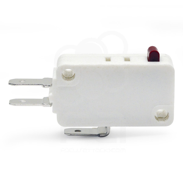
These particular USB encoders were guaranteed to work with the Raspberry Pi, with almost no additional configuration. Everything is pretty much plug-and-play, and this kit is a good way to get everything you need in a single purchase. That being said, I wasn't completely satisfied with the microswiches the kit comes with. They aren't horrible, and they will work, but the satisfying "click" and response from the buttons just wasn't as crisp as I was looking for, so I turned to FocusAttack for some better MicroSwitches.
It is a pretty great website for all your arcade setup needs, and you can pick from a huge selection of different buttons, switches, joysticks, and USB encoders. The Kit on Amazon works, and makes purchasing simple, but I wish I would have picked everything out from FocusAttack from the beginning. I did end up getting a few additional colors for my buttons, and replaced all of the switches from the Amazon kit with the E-Switch 50g .187" Microswitch. They are pretty inexpensive at .95 cents each, and gave my buttons the "click" I was looking for. They also gave the buttons a bit more resistance, which was the main thing I thought the kit switches were lacking.
Once all the parts had arrived, it was time to start laying out the design for the control board. As mentioned before, I didn't use the control layout from the StartCade project, but made my own using various reference designs found online. I made it to scale in PhotoShop, then printed it out on 2 pieces of paper. Before cutting into the MDF boards, I decided to do some prototyping on cardboard, just to ensure I was happy about the button spacing before omitting to anything. Used a drill press to punch holes through the template and cardboard.

Once I installed the buttons and joystick on the prototype setup, gave it a quick test. They layout seemed to work well so went ahead and transferred the dimensions to the MDF.

This is the template for both the controller board, and the front of the arcade. The controller board layout I went with for a 2 players setup is made up of a joystick, 6x action buttons, Coin, and Player buttons. Coin can also serve as "Select" and Player can be "Start". For the front, there are various menu and option buttons, which will make more sense when the artwork is applied behind it with labels in the required locations.

The holes for the buttons are roughly 29mm. I used a 1-1/8" forstner bit so each hole is nice and smooth. Also had to drill a few holes to secure the joysticks to the board.

To secure the joysticks, using 8-32 x 1in black screws. Also countersunk the holes so they wouldn't touch your hands when brushing across the surface of the board.

Here is a sample of what the hardware will look like when installed on the board. Coming along pretty well at this point. The blank hole on the top will be the "Pause" button. The lower board will be the front of the arcade. As mentioned before it will have various menu, and option buttons. Also shown installed are USB input extensions. This will make it easy to hook up a keyboard for future configuration, or USB controllers if the kids want to use one for a specific game.

USB Encoder Wiring
Now its time to start wiring the buttons to the USB encoder. The cables that came with the kit aren't very long, so I may have to re-position the USB encoders before all is done.

Here is a closeup of how I wired everything. Pretty straight forward, but I did have to move around the direction of a few switches to reach the encoders.

There wasn't a wiring diagram provided with the kit, so a bit of trail and error was involved. Once I had it wired the way I figured it would work, had to test it out. Attached the board via USB to the Raspberry Pi, and attached a small LCD monitor via HDMI. Luckily everything worked as it should on the first try. Sampled the configuration by playing the NES classic, "Contra".

Arcade Display
Now wanted to go over what I will be using for the Arcade display. Going 4:3 instead of widescreen, as every game on this emulator was made before widescreen TVs were common, so there will be no pixel distortion.Initially I was planning on purchasing a display, but wasn't happy with the prices I found for old 4:3 aspect ration LCD monitors. So instead I popped in to a local thrift store, and found this beauty for only $7!! A ViewSonic VG930m, 19in monitor. Not a scratch on it, and no dead pixels. Comes with built in speakers, but won't be using those. It doesn't have HDMI, but planning on using a HDMI to DVI cable for the signal. The stand can be removed, and it has a VESA mount to secure it to the cabinet. Great find!

Now that we have the rest of the hardware covered, time to move on to the cutting, sanding, painting, and assembly of the rest of the cabinet.
No comments:
Post a Comment