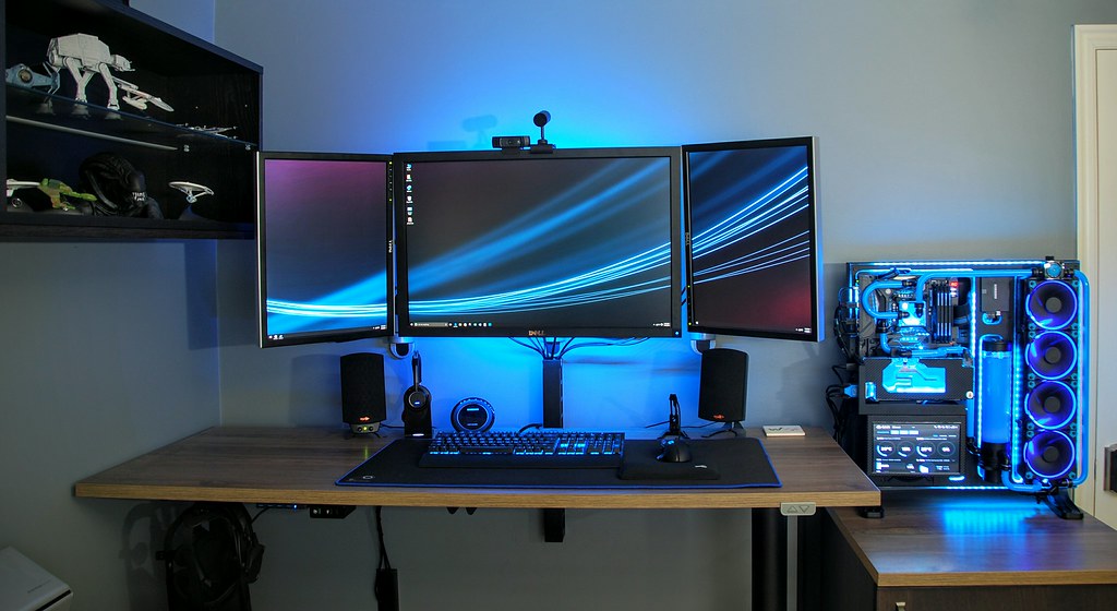
I also have received more questions about that particular part of my system than any other post both on this blog and my YouTube channel. So I decided to upgrade that particular component, and archive the entire process. In addition to the info on this post, I will also make an overview video and posts it at the bottom.
The previous display was a 9in LCD panel. The new one, is a Toguard 10.1 Inch IPS display. Here is the Amazon Link. It is almost twice the cost of the 9in one, but the panel quality is a LOT better, so worth it in my opinion.

Here is a picture from the back. The 9in was a bit easier to mount as it had a camera/tripod mounting hole, that I secured it to the GPU bracket with. This new display has no such mount, but does have 4 mounting holes on the back of the display.
From the bottom you can see the various connectors. All I am concerned with are the 12V DC power port, and the HDMI input.

The front plastic made to look like brushed aluminum. I probably would have left it as is, if it weren't for the TOGUARD logo. So I covered just the front bezel with my Carbon Fiber Vinyl wrap.

I gave it a quick test before making the mounting bracket just to verify everything would work the way I needed it to. Here we are showing connections from the PC to the Display. Note the 12V DC plug is coming directly from a 4pin Molex connection that I wired specifically to power this display.
The initial tests passed with flying colors. Not yet mounted, but running CAM perfectly. On to the mounting bracket construction.
To make the bracket, I grabbed some sheet metal that I had left over from another project. I measured both the exterior dimensions and the location of the mounting screw holes.
Once I had everything marked, cut out the piece, drilled the holes, and used my bench vise to make a nice 90 degree bend to accommodate mounting the display under the GPU bracket.
To secure the display to the mounting bracket, I am using M4-7 socket cap screws, and a few washers. The length was a bit too long, as the mounting holes were not very deep, so I used some nuts to shorten the length of the screws.
After everything was drilled, cut, and bent, added a few passes of black spray paint to match the color theme of the PC build. Also shown here is the 6mm screw I used to secure the mounting plate to the GPU bracket.
Here is the hole I drilled in the GPU bracket.
And here is where the 6mm screw will go.
With the mounting plate secured the the GPU bracket, we can now attache the display.
Here is a shot from the back to show how the screws are securing the display to the case.
And a final shot from the front to show the new upgraded display installed and running CAM.
I will show in the video more detail on how to get the NZXT CAM Monitoring software up and running, but just for reference, here is what my displays look like, with this new on set up as the 4th monitor of my system. Desktop Screen Capture of all 4 monitor.
Here is the video. If you have any questions be sure to hit me up in the comments. Thanks!
If you need to go back and take a look at other posts for the this build, here is a quick navigation index you can utilize.


