Project Blog Pages

Friday, December 15, 2017

Review - NESPi Case for Raspberry Pi Console & Arcade Emulator

I have been building mini Emulator Consols for a few years now, and not much has changed in case design. They all house a Raspberry Pi, and give access to the required I/O Ports. They have worked fine, but were pretty simple in design and apperance.

I recently came across a new case that really takes it up a step in quality, presentation, and functionality. Meet the NESPi Case for the Raspberry Pi (Amazon Link).  It will house a Pi B+, 2, and 3.  Aside from a pretty well built case quality wise, it does 3 things that no other case I have seen has been able to achieve, especially at this price point.
     1) It has working Power and Reset buttons in the front of the case
     2) Working LED indicator when the system is powered on (usually I have to add this via a mod)
     3) Reorientation of Port to for a better look and easier cable management

Here is a side by side comparison of some other Pi cases I have to give you a better idea of how large it is.  It is a tad bigger than normal Pi cases, but nothing even close to the size of the original NES console which it mimics.


By using a series of breakout boards, all 4 USB are located in the front, 2 in the where you would normally plug in your controllers, and 2x hidden behind the hinged lid along with the Ethernet port. Power and HDMI ports have also been relocated to the back of the unit. Shown here is everything that comes with the case, including the very simple instructions (Rapsberry Pi does not come with the case).


Here you can see where the Pi installs next to the breakout boards.


And again a view from the front showing the USB and Ethernet ports.


Here you can see the functional LED indicator showing the system is powered on.


And here are views from all the sides of the unit.


Overall I am very pleased with this case, and it is now my "go-to" for my personal systems and those I build for friends and family. For a more detailed walkthrough and to see this particular unit in action, check out the video below.


Monday, October 2, 2017

Prusa i3 MK2s 3D Printer Upgrade Timelapse Video

I have been planning on upgrading my Prusa i3 MK2 to the MK2s version for a while now.  After the MK2s was annouced, I set forth to get the required components. Most of the 3D Printed parts were readily available on the Prusa web site, but I also found a few upgrades (Aaron Yourk's TinkerCAD page) that I wanted to include this time around. Here is a full list of what I decided to modify.
  • Upgraded MK2s Extruder Assembly with Cable Chain adapter
  • New E3D V6 Hotend (last one was pretty messy)
  • Upgrade to 40mm Noctua Extruder Fan and housing
  • Upgraded Cable Chain for Extruder Cables
  • New Y-Axis frame helper to keep things square
  • New Misumi Bearings
  • New Misumi Hardened Rods
Here is a pic of the current MK2.  Has been operational for around 7 months, and prints really well. Very happy with it, but I know from user feedback better bearings and rods will make for quieter operation and possibly allow for faster print times.  


I have a bunch of picture following the process, but if you are just interested in the timelapse video, jump to the bottom of the post.  For anyone interested in the Misumi parts, here is what I purchased:


Here we have all the  parts that will go into the upgrade. Anything around the extruder where it will get hot were printed in ABS, the rest are PLA. 


Here is a close up of the parts.


First step was to take apart the existing printer and start assembling the new frame. The upgraded Y-Axis front and back make the entire process much easier, and there is no room for error as it keeps everything nice and square. This is a great upgrade because getting the frame perpendicular was a real challenge with my first Prusa i3. 


With the frame assembled, I got to work on the X-Axis components and extruder assembly. Most of this would be stock components aside from the new 40mm Noctua Fan and Fan Guards. 


Went through the process of attaching the extruder assembly to the X-Axis and leaving the cables behind, awaiting the addition of the cable chain.  As mentioned before I decided to install a new V6 Hotend, as the last one was pretty messy after a few print failures that caused the filament to backup. 


Same but from the front. 


Here is a shot from the back showing the cable chain.  I actually added a few more links (24 total) than what are shown in this picture after testing operation and determining I needed more for it to not bind during certain points of movement. 


Here we have the fully assembled printer in a side by side comparison withe the previous MK2 configuration. I think the Black / Blue color combo looks a lot better. 


Went through the initial calibration process, and we are Perpendicular after the first try!  Last time it took me a while to get here, so the upgraded parts are already doing their part in saving me time. 


Here is a pic of everything put back into the print Enclosure, ready to start printing. 


My very first print was the TreeFrog Gcode found on the SD Card.  It printed well, so I moved on to some "functional parts". Below can be seen a few parts that will go towards upgrading my Quad Racing Drone. Turned out perfect. Print quality is excellent, and operation is a bit more quiet. 


Very happy overall with how the upgrade turned out, and was also able to capture the entire process with my Nikon D5600 in a Timelapse video. Check it out below. 


Monday, September 25, 2017

DeathTrooper (3D Printed) Storm Trooper, IWI Tavor, and Tannerite

For this project, I had a chance to collaborate a bit with my brother and his buddies at their YouTube channel, How2Man

I have an IWI SAR Tavor, which is a really fun 5.56 bullpup rifle, and thought it would be great to showcase this weapon for this collaboration video, and use it to destroy a 3D printed object using Tannerite.


I found an excellent STL of a DeathTrooper online, which is basically a Storm Trooper helmet that shows a bit of battle damange, and the skull inside.  I increased the size of the print to better allow for us to fill it with around 2lbs of Tannerite.


The entire print took around 36 hours to complete, and once done looked absolutely AWESOME!  I was almost sad that we were going to blow it up... almost.


I added a tad of acrylic paint to make the skull more noticeable. Also drilled a small hole in the bottom of the helmet so we could pour tannerite into the hollow portion.


Here is a short video showing the print and a 3D Render of the object.


And here is a longer video showing the process we went through to fill the helmet and detonate it using the Tavor. There is some cool slow-motion in addition from some drone video from my 3DR Solo. Enjoy!


Solar Eclipse Pics & Celestron Telescope Filter (3D Printed)

The August Solar Eclipse was an amazing event. Luckily for us, we were only a short 3 hours away from Totality.


In addition to watching the eclipse with my family, I wanted to use my telescope to better see the the event. I have a Celestron NexStar 127STL, which is roughly a 5in Maksutov-Cassegrain. I was surprised after looking on Amazon and B&H Photo, in the lack of available slide-on filters for this size of telescope. So I set off to design my own.

The most important part of this “make” is the ability to block out the harsh brightness of the sun, so I grabbed an appropriate sized solar film. I found a 6in x 6in film on Amazon for around $15.

With that selected, I set out on the slide on filter design. It consists of 2 parts.

  • Primary cap to slide over end of telescope and hold the film
  • Secondary ring to hold film against the larger cap 

Pretty simple to create after measuring the telescope and creating the initial design in SketchUp. I also chose to add some clips to the outer cap to keep the inner ring snug against the cap, therefore keeping the film in place.


With the design completed I printed the two parts, and cut the film to fit inside the outer cap. The print came out great, and for perfectly over the 127STL.


Problem is, this was printed in PLA and I was worried that the hour leading up to the eclipse, would be too hot for the PLA to handle. Reprinted both parts in ABS.

With the final print completed, we drove to St Anthony, ID and set up camp. We were part of a sizeable viewing party, And I began taking photos with my camera about an hour before the eclipse actually started, and let people come up and see the sun in all it's filtered glory in the telescope. Sun Spots were easily visible.


The eclipse began, and a hushed silence and twilight darkness was ushered in as Totality approached. Once we hit full totally, I pulled the filter off, and was a amazed at the detail that was visible,especially the colorful corona  around the eclipsed sun. In person it was amazing, but I wasn't able to really capture it with my DSLR or through the telescope with my phone. I decided to stop messing with it, and just enjoy Totality with my family.


After the event, we drove home and I began to sort through the photos. After minimal editing, I had a pretty good “Timelapse” of the eclipse process.


Here is a modified pictures with the key eclipse phases placed next to each other.


Overall the print worked perfectly, and I will hold onto it for future Sun viewing. Also want to invest in a better camera mount for better pictures, and will be sure to post an update once I have something to show.

Not really eclipse related, but I was able to get some pretty good long exposure shots the night before.


Thanks for stopping by!


Monday, July 24, 2017

Cryptocurrency Mining Rig Build – 2nd Rig & Video Overview

Project Index:
I was able to get my 2nd Rig up and running, showing the "stacked" configuration of my case design.


The hardware is identical to the 1st one, but instead of 1060s I am running 6x GTX 1070s.  Here is the component list for the 2nd Rig.

In addition to higher hash rates (average 32Mh/s per card), they generate a LOT more heat.  Had to install a 4x fan setup to push the heat away towards the room's exhaust vent.


Here are the videos I put together outlining the entire process.


Thanks for looking!

CryptoCurrency Mining Rig - Performance Tweaks to Maximize profitability

Project Index:

With the hardware installed, on to the software portion of this build. Installing Windows 10 on the M.2 SSD is the same as any system, using a USB connected DVD drive or better yet a USB drive configured to install Windows.  Don’t worry about drivers, as any modern motherboard with 6 PCIe lanes should handle driver installation automatically during the installation process.**

**Note – You may have to modify certain settings in your system BIOS to allow for the use of 6 GPUs at the same time within Windows.  Refer to the manual for your specific motherboard for details.

With the particular Motherboard I am using, I had to make sure the following settings were configured as shown below.

Verify that BIOS settings are as follows:

  • Windows OS > Windows 10 > Enabled
  • PCI Settings > 4G > Enabled
  • PCI Settings > PCI > Gen1

The following are the tips that work for my system specifically, and may not necessarily be the best thing for your build, but maybe it will help you in some way.

Once Windows has fully installed, you want to run Windows Update and ensure that Windows Anniversary Edition update is installed. As of July 2017, if you are fully up to date, you will have that update as well.  Once all of the updates are completed, give your system a reboot, and then check out the Device Manager and ensure that all 6 GPUs are showing up.


If all the GPUs are showing up, we can assume that Windows automatically installed the correct GPU drivers, and its time to see if mining works properly with these cards. For my situation, installing the most up to date NVIDA GeForce drivers from Nvidia’s website actually made my mining performance worse, so I have been using using the drivers installed automatically by Windows instead.  If your cards aren’t showing up, or you are experiencing poor mining performance, best to uninstall graphics drivers using the DDU (Display Driver Uninstaller) utility, and let Windows reinstall the drivers after reboot.


There are various mining applications you can run, along with mining pools you can join.  I chose to go with NanoPool and use Claymore’s Dual Miner to mine Ethereum. There is some configuration that will need to be done, but nothing too difficult. Once everything is set up, lanch the .bat file to start mining Ether. Off the bat, stock GTX 1060s will get between 18-19 MH/s. With a little bit of overclocking I was able to get on average 22 MH/s per GPU, and also reduced my power draw.


I was surprised to find that with this “under-clock” of the GPU, this system is only pulling around 35 watts from the wall when idle, and around 560W from the entire systems during mining operations. Not bad at all, considering I am getting a combined total of 132 MH/s from this system.


At this point you are pretty much done.  I do recommend installing some monitoring  / remote access software to check on the system when you are away. With everything up and running, you can just leave it alone and it will keep mining away.  As long as there is sufficient cooling, it should be pretty maintenance free, and can run for weeks at a time without any issues.


Thanks for taking a look at my project blog, and hit up the next post if you would like to see a video overview of the entire build process. I will also be building a 2nd system in the following weeks with GTX 1070s! So take care, and be sure to check back. Thanks.

CryptoCurrency Mining Rig - Parts List & Assembling the Ethereum Rig

Project Index:
For this post, I am just going to go over the components I used for the build. Not really going to do into detail on how to put the parts together, as it is no different from a normal PC build, and there are TONS of other resources available for that. I will just focus on things unique to this case and Cryptomining specifically.


Here is the component list for this build. As mentioned before, the GPUs are from 3 different manufactures, but they are all GTX 1060s, so linking their Overclocking profiles will still be easy to do.  All of these links will take you directly to the product on Amazon.  I will list a few options around the same price for the GTX 1060 GPUs, as availability is pretty rough right now. Which ever video card you go with, make sure it has at least 6GB of video RAM, as the DAG file for Ethereum will surpass the 3GB threshold very soon.
The following are nice to have, but not required. Helpful with troubleshooting and remote system management. I will also go over my methods for remote management in a future post.


Most of these parts are interchangeable with other components, so feel free to shop around if you think you can find a better deal with a different component. At the time of purchase, these were the best price for performance.  The Motherboard specifically is a good buy for the price, and works great with 6 GPUs with little effort.

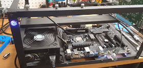
For the most part, assembling this rig is the same as any PC. You will add the Power Supply, Motherboard, M.2 SSD, Processor and RAM.  Some people choose to just have the motherboard sit on top of the wood planks, with rubber bumper feet underneath.  I wanted things a bit more secure, so I added motherboard standoffs to the wood planks, and attached the motherboard to the standoffs with thumb screws. No need to use a ton of standoffs since the motherboard will not be sitting vertical, 4-5 should be plenty to keep things secure and supported where needed.


I also decided to add an illuminated latching switch the build. I could have just used one of these jumpers, but I wanted something that looks a bit nicer, and could be secured to the case. You just need something that will power on and off the case, and having an LED indicator is nice but not necessary.


You can choose any size you want for the button, I went with a 16mm.  Drill the mounting hole wherever you plan on having the button. Thread the button in place, and then attach the cable to the front panel headers according to the specifications of your motherboard.


The final component that is unique to this type of case is the need to use PCIe riser cards for the GPUs.  As there is not enough room or or enough PCIe x16 lanes for 6 GPUs, so we use these adapters.  This particular motherboard has 2 x16 PCie lanes and 4 x1 PCIe lanes.


We plug the x1 adapters in these lanes, and then connect the riser card to the GPUs via a USB 3.0 cable.  I prefer to use the angled USB adapters here, as there is less stress on the connectors and cables with this configuration. The pictures below should make all of clear.


With the riser cards installed, and the GPUs mounted, the build is pretty much done.  As I mentioned earlier, this design is stackable, so I wanted to show how I will be achieving this so I can add a second mining ring in the future. You can’t stack the cases directly on top of each other, as there won’t be enough room for the GPU power cables between them. You will need some sort of risers between the cases. You could probably use rubber stool feet or something similar, but I designed some standoffs to work with the 3/4in aluminum, and used my 3D printer to make them.


Here you can see how they will attach to the case, allowing for the stackable design.


And here is what the 2 cases together look like on top of the stand I built earlier.  As you can see, plenty of clearance for the GPU power cables.  Now on to software and mining tweaks.


Next up, I do a run down of performance tweaks to get the most out of your mining rig.