Saturday, May 28, 2016

Project Open Core: LED Lighting & Acrylic Testing

I was pretty sure that going with an RGB LED strip was the way to go for this build, until  someone introduced me to EL Wire.  In concept is seemed like a great fit as long as you got the right color as you cannot change it on the fly like you can  with RGB LEDs.

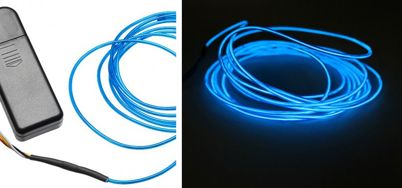
So I purchased some Blue EL Wire to try it out.  It would have worked great in regards to the install, as it is much smaller than the LED strip, and would easily bend around the curves in my acrylic panel. The brightness level was pretty low, but that was fine as I just wanted a subtle glow and not glaring lights. The problem was the whine… a high pitched, very annoying electrical whine.  I even purchased a different transformer hoping it would fix the problem.  It was a tad quieter, but still not something I could have going next to me a few hours a day.  So threw out the idea of using EL Wire.


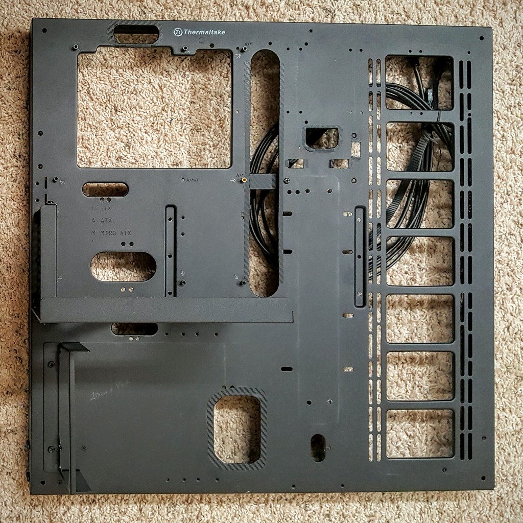
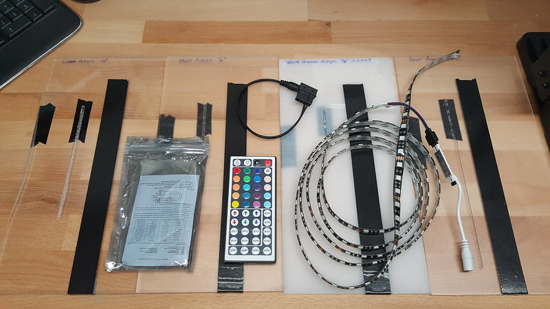
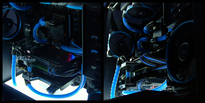
Aside from the electronic whine, the decision to go with the LED strip was also driven by the fact that the ASUS ROG Maximus VIII Formula has an RGB header allowing my to sync an RGB LED strip to the other colors emitted from the Motherboard. That kind of customization cannot be achieved with EL wire, so I went with a 6ft RGB LED kit that included a 44 button IR Remote and 4pin MOLEX to a 12V barrel plug adapter. The back of the strips are adhesive as well.  I played around with the different color options, and the flexibility of this kit is excellent.


Now to rewind time a bit. Before I started cutting my acrylic panel, I and to decide which type to go with. When deciding on which type of acrylic panel to use, I tested the following plastic samples:

  • 1/4in Clear
  • 1/4in Frosted
  • 1/8in Clear
  • 1/4in White 

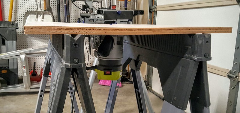
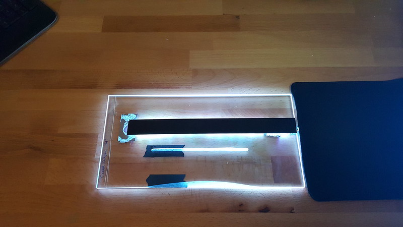
I cut a “U” channel into each piece and also shaved a beveled edge on on side. Placed the LED strip behind the panel and fired up the lights to see which gave off the right amount of light around the edges.

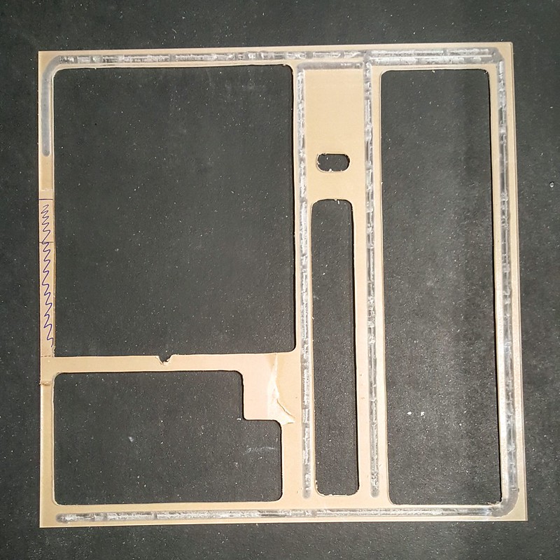
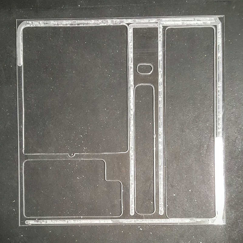
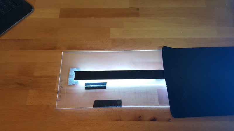
First up is the 1/4in Clear. Since you have already seen the larger version, you know this one was the winner.  It had just the right amount of light transmission along the edges, and was thick enough for me to shave a 45 degree bevel so the light around the edges shines up and not just out.


This is the 1/4in Frosted sample.  It was ok, but diluted the light a bit too much around the edges.


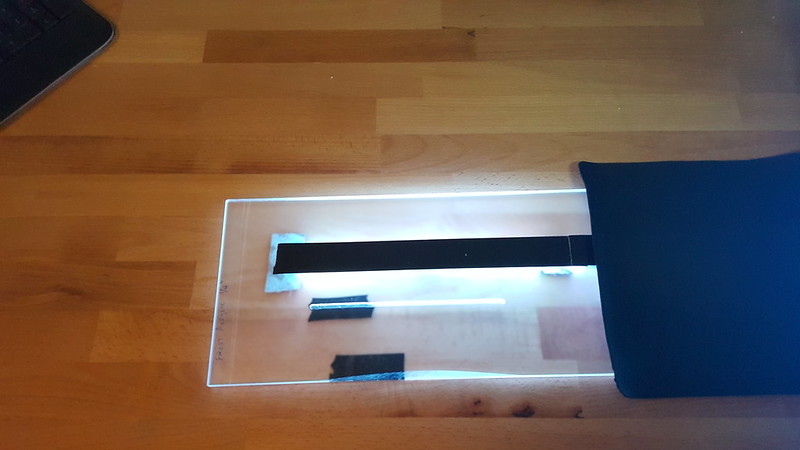
Same as above but 1/8in this. Found this to be too thin for me to use at all.


Last up was the 1/4in White sample.  I actually thought this would work really well, as I have used they type in my last build, and it did really well.


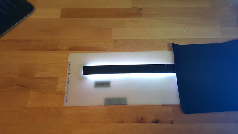
The difference is that in the last build, the objective was for the light to shine up through the panel, and not out around the edges. Turns out the white panel doesn’t do the edge glow well at all.


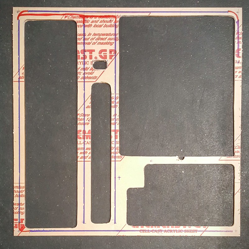
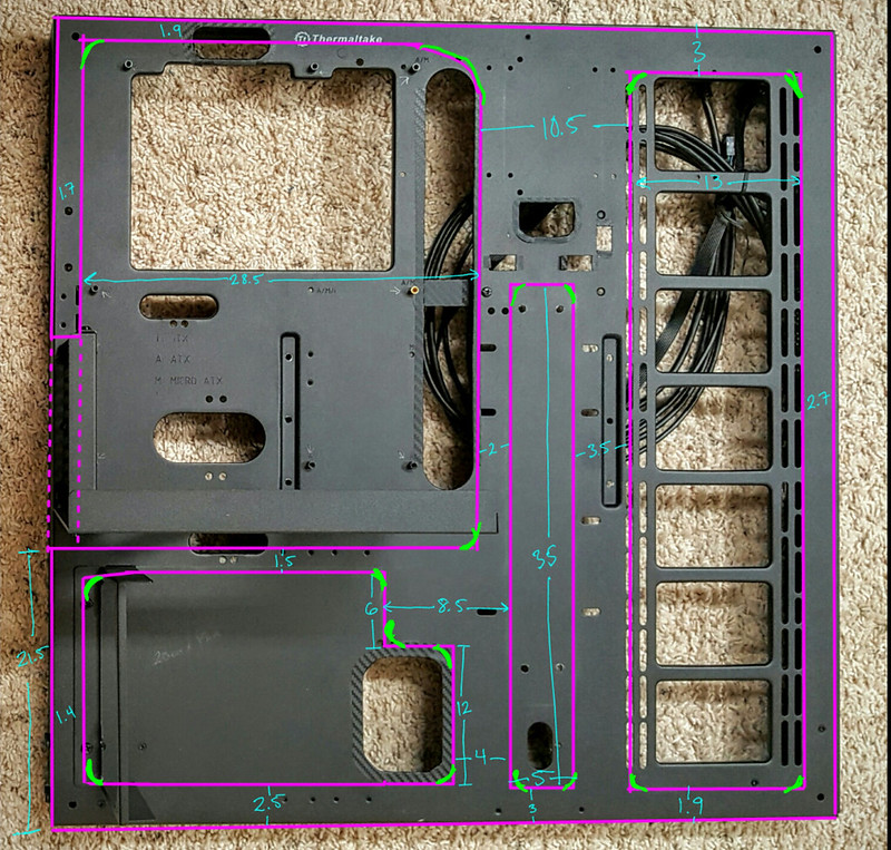
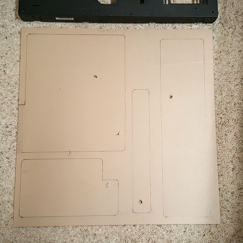
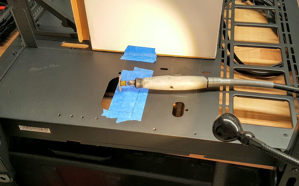
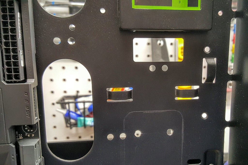
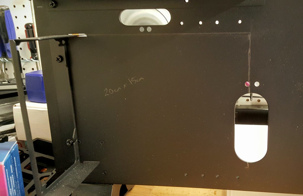
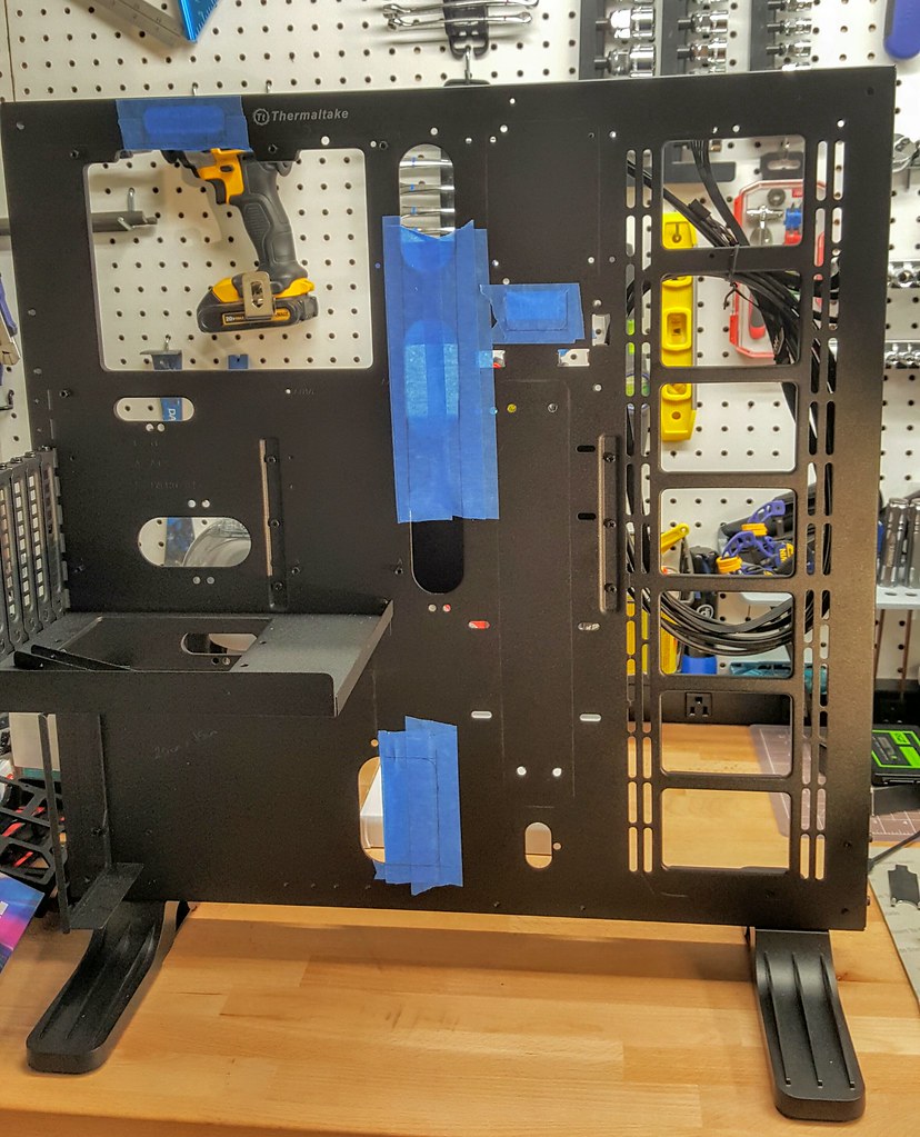
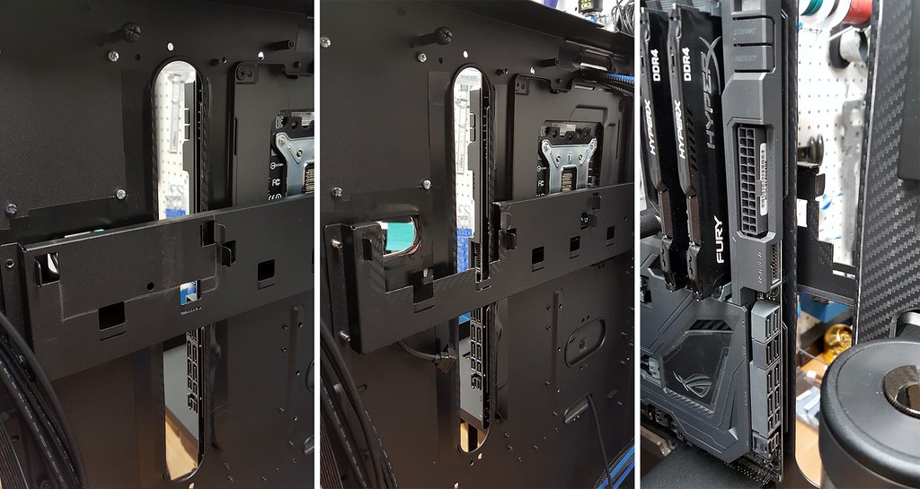
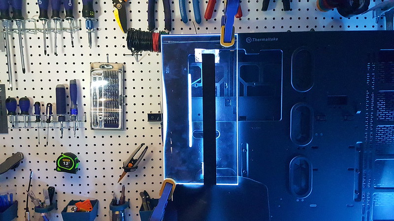
So with the winner selected, I purchased a 24in x 24in panel, and got to work as shown in the previous posts.  Here is a picture of the sample that I was playing with to make sure it would give me the desired glow.


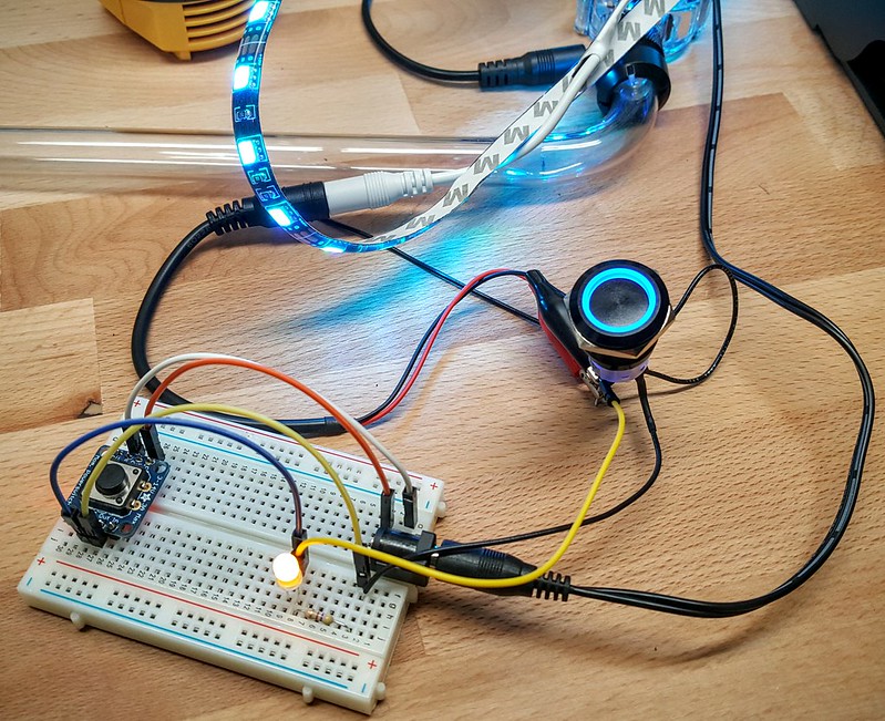
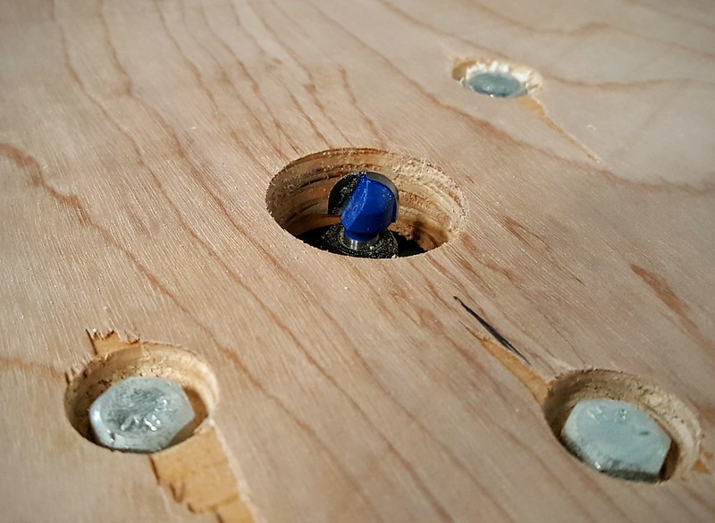
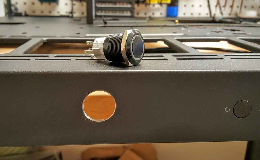
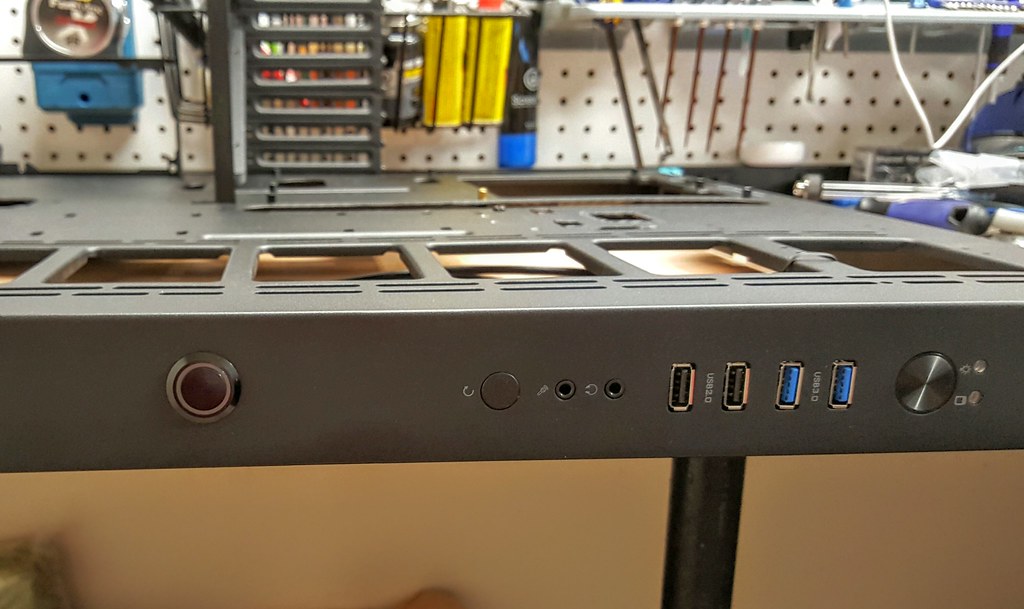
I also had to make sure to get the wiring correct for the latching vandal switch that will be used to turn on and off the LED strip.  The switches I used in a previous build couldn't take a direct 12v current. So I tested this one using a breadboard with a resistor so I wouldn't accidentally burn it out. After a bit more research, this one in particular can in fact take a direct 12v load, so no need for the resistor, and it will be wired into the case after I install the LED light strip.


Thursday, May 26, 2016

Project Open Core: Acrylic Light Panel - Cutting continued…

In order to get the light transmission I'm looking for from the LED light strips that will be used, the strips need to be set inside the acrylic. This will also allow for a flush install of the panel on the front surface of the case. I decided to use a router for this purpose, with a rounded bit to carve a “U” shaped channel that matches the shape of the light strip.

Here is the concept I drew up on my tablet of where the light strips will be located.


Picture showing the lines that will guide my routing efforts.


Here is the platform where it will happen.  Similar concept to the cutting table, and qorkwd really well for the intended purpose.


Quick peek of the routing bit.  The router itself was attached to the table using bolts that were countersunk as to not interfere with the panel while it moves along the surface.


Here is the aftermath of cutting / carving out the U channels. It went well and there were no issues.  I considered using my Dremel tool to smooth out the channels afterwards, but found out that doing so actually affects the light diffusion in a negative manner, so left them as is.


Removed the protective cover and now ready to do a bit more clean up before adding the lights.  The channels that were cut are not only for the light strips, but also for the wires that will connect the various runs.


Project Open Core: Acrylic Light Panel - Cutting

As mentioned earlier, one of the custom aspects of this build will be a light emitting Acrylic panel that encompasses the entire front panel of the case, with cut-outs for the components to sit inside.  The idea is the panel will “glow” around the components as well as the outline of the case itself.  I went through a lot of testing to figure out what kind of acrylic panel to utilize for this feature along with different lighting sources, and will cover that in a future post. For now, going to show what I did to shape the panel for this build, in preparation for adding the lighting.  

Below are the measurements I used to plan out where the cuts would be in relation to the components and existing cut-outs in the case.


Starting off here is the Panel.  It is 0.25in thick Clear Acrylic, and the dimensions are 24in x 24in to fit this case. I entertained the idea of using the acrylic that came with the case, but it seemed more ridged and brittle, so decided against it, and picked up this one for under $20 at a local plastics shop. I went ahead and outlined where the primary cuts will be, based om the location of the components.


I will be fashioning a jigsaw cutting table and picked up these blades to help.  They are specifically made for plexiglass, and have less risk of chipping or cracks when cutting. Starter holes were drilled into the panel before cutting with the jigsaw.


Here is the cutting table. Pretty simple, just bolted the jigsaw underneath, with the blade poking through just enough to cut the acrylic. I used ripsaw guide clamps to try and maintain straight cuts, but even with those in place it was still difficult keeping those lines were they should be.


The cutting went well overall, but as mentioned before, had some challenges with straight lines.  Will definitely have to do some Filing cleanup work to make the appearance acceptable.  Was a little worried when cutting around the areas that thinned out, but turned out to be pretty easy to manage those cuts which was a welcome surprise.


Here is what the panel looks like when applied to the case.  The larger cut-outs will be for the Motherboard, Radiator, Power Supply, and Reservoir.  Lots of cleanup work still needs to be done, but first on to cutting the channels out to male room for the LED strips.


Wednesday, May 25, 2016

Project Open Core: Case Mods

I have been wanting to start a new build for a while now, but none of the cases available were really what I was looking for. I had also been toying with the idea of doing a “Computer Desk” build for a while, but something always stopped me from going down that path.  With the release of the Thermaltake Core P5, I found something that had a unique look, and the open nature of the case allows for so many custom options.


It's a very large case, about the same dimensions of the Corsair 800D I am currently using.  It also has the option to be wall mounted, but I’m not comfortable doing that with the added weight of a liquid cooling loop. It might work fine, but not a risk I am willing to take.  I also feel the case is the best I have seen for displaying the beauty of a well set up liquid cooling loop.  The fact that you can also install a GPU vertically is a big plus.  I nice looking GPU Block is great but with most systems, you can’t really see it, and I am glad the Core P5 has addressed this.


As far as modding goes, I originally thought there wouldn't be much need to do much….
Turns out I was wrong. For most, it probably doesn't need any modding, but for what I am looking to do, it was time to bust out the Dremel Tool.


There are various cut-outs around the case for cable routing, and they are not few in number.  I was glad to see this, but I quickly found out that a few of the cut-outs don’t line up will with my hardware, and would have to be altered. First up, is the location where you can mount an SSD to the front panel. The existing hole is a bit too tight for my liking to route a SATA cable, so it needed to be enlarged.


Next up is the power supply. I am using a Corsair AX1200, and it seems to be a bit longer than average. Because of this, the PSU would cover up about half of the cut-out, which would make it difficult to bring sleeved cables through. Needed to increase the size here as well.


The cut-out at the top of the case to route the 8pin CPU Cable had to be altered because of the acrylic light panel I was building.


Also had to increase the size of the cut-outs along the Motherboard to have clean bends with my sleeved cables.  This may not be an issue with other MoBos, but the 24pin location on the ASUS Maximus VII Formula didn’t line up well with the existing cut-outs.  It would have still worked, but to get the look I was going for, needed to be altered.


The cutting went well, and I will now have a bit more freedom to route cables specifically the way I want.  Structural integrity of the case seems to be fine, but as mentioned before, no wall mounting for this build. Then went ahead and filed down the cut edges to be smooth, and as a precautionary measure, also wrapped all cut edges with a carbon fiber patterned adhesive vinyl.


Ended up making 1 additional cut along the HDD support bar.  Reason was again to provide easier routing of 24pin sleeved cable.


Even though the ASUS MoBo can control the system lighting, I wanted a push button switch to turn the lighting effects on and off.  Will be using a 22mm Blue Illuminated Vandal Resistant "Latching" Switch for this purpose.


Used a Step Drill Bit to make the hole.


It seems to have  slipped a bit and its not perfectly centered, but not much I can do now, and it still looks fine.


Next up, custom lighting and acrylic testing!


Project Open Core: My Workspace

Recently moved into a new home, and there was a weird “closet” that is attached to the room that was to be converted into my home office. My wife had the idea to turn it into my project room, and it has worked out really well so far. Aside from PC modding, I also use it as a firearm cleaning station, and a place to work on my Quadcopter Drones / RC Cars. This picture also serves as my digital vault.  If any tool goes missing, I can reference this photo as a reminder of where it goes... after I track down whomever "borrowed" my tool.


My garage will also serve as a “workspace” for the messing cutting and routing parts of the build, but its just a normal garage and doesn’t merit any photo uploads.

Tuesday, May 24, 2016

Project Open Core: Build Components

I am simplifying the liquid cooling loops compared to my last two builds, as I am no longer going to be running SLI.  With a single GPU (GTX 1080) I will be using 1 loop to cool the CPU, Motherboard, and GPU.

Here is the Component List:

  • Case: Thermaltake Core P5 Open Air Case
  • Power Supply: Corsair AX1200
  • Motherboard: ASUS ROG MAXIMUS VIII Formula
  • Motherboard Block: EK Integrated Crosschill MOSFET cooler
  • CPU: Intel i7 6700K
  • CPU Block: EK-Supremacy EVO Nickel
  • RAM: 32GB Corsair Dominator DDR4 @ 3200MHz
  • GPU: EVGA GTX 1080 (SC, SSC, FTW… waiting for release to know for sure)
  • GPU Block:  EK 1080 Acrylic + Nikle (not yet released) 
  • Sound Card: SupremeFX 2015 (On-board)
  • Hard Drive 1: Samsung Pro 950 256GB M.2 PCIe SSD (Operating System & Programs)
  • Hard Drive 2: Samsung Evo 1TB SSD (Games & Steam Installs)
  • Hard Drive 3: Seagate 2TB HDD (User Files)
  • Hard Drive 4: Seagate 4TB HDD (Storage)
  • Optical Drive: Samsung Blu-Ray / DVD+R (External USB)
  • Pump & Reservoir: XSPC D5 Photon 270 Reservoir & Pump Combo
  • Radiator: Alphacool NexXxoS 480
  • Coolant: Mayhems Pastel Blue Concentrate + Distilled Water
  • Tubing: Monsoon Hardline PETG Tubing 1/2" ID, 5/8" OD
  • Bending & Cutting: Monsoon Hardline Cutting & Bending Kit, Barrows Bending Tool 
  • Fittings: Barrows Matte Black... and lots of them
  • Case Lighting:  LED Strip 8ft 5050 RGB + 44 Key Remote
  • Acrylic Panel: 24in x 24in x 0.25in clear
  • Sleeving Material: MDPC-X (MurderMods) Sleeving Kit; Black, Blue, Heatshrink
  • Fans: Thermaltake Riing 120mm Blue LED Fans (x4)
  • Fan Controller: Phobya 4Pin PWM to 4x 4Pin Fan Splitter, ASUS AI Suite Software
  • System Stats Display: Toguard 10.1 Inch IPS display


This may change a bit as I get going, but for now it's pretty solid as I have most all the parts except for the GPU and accompanying block which haven’t been released yet.